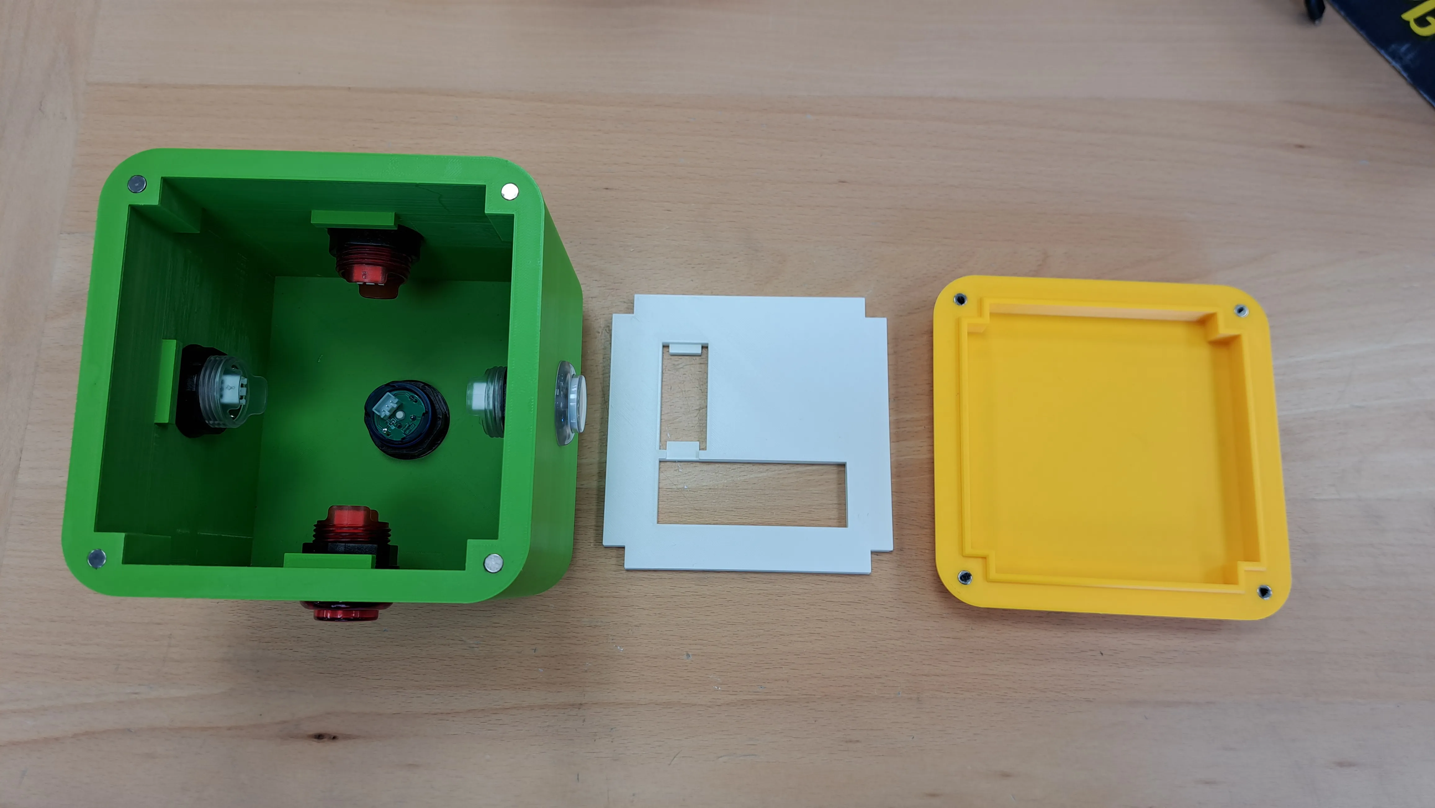
For some GCSE subjects, including AQA Engineering, students have to complete a “Non-Exam Assessment” (NEA). Our task was to build a hardware project around the theme of “Interactive Toys”. Inspired by some toys I’ve played with as a kid and some video games, I decided I would make a “memory game” toy which would give the user a sequence of increasing length and ask them to repeat it.
Design ideas
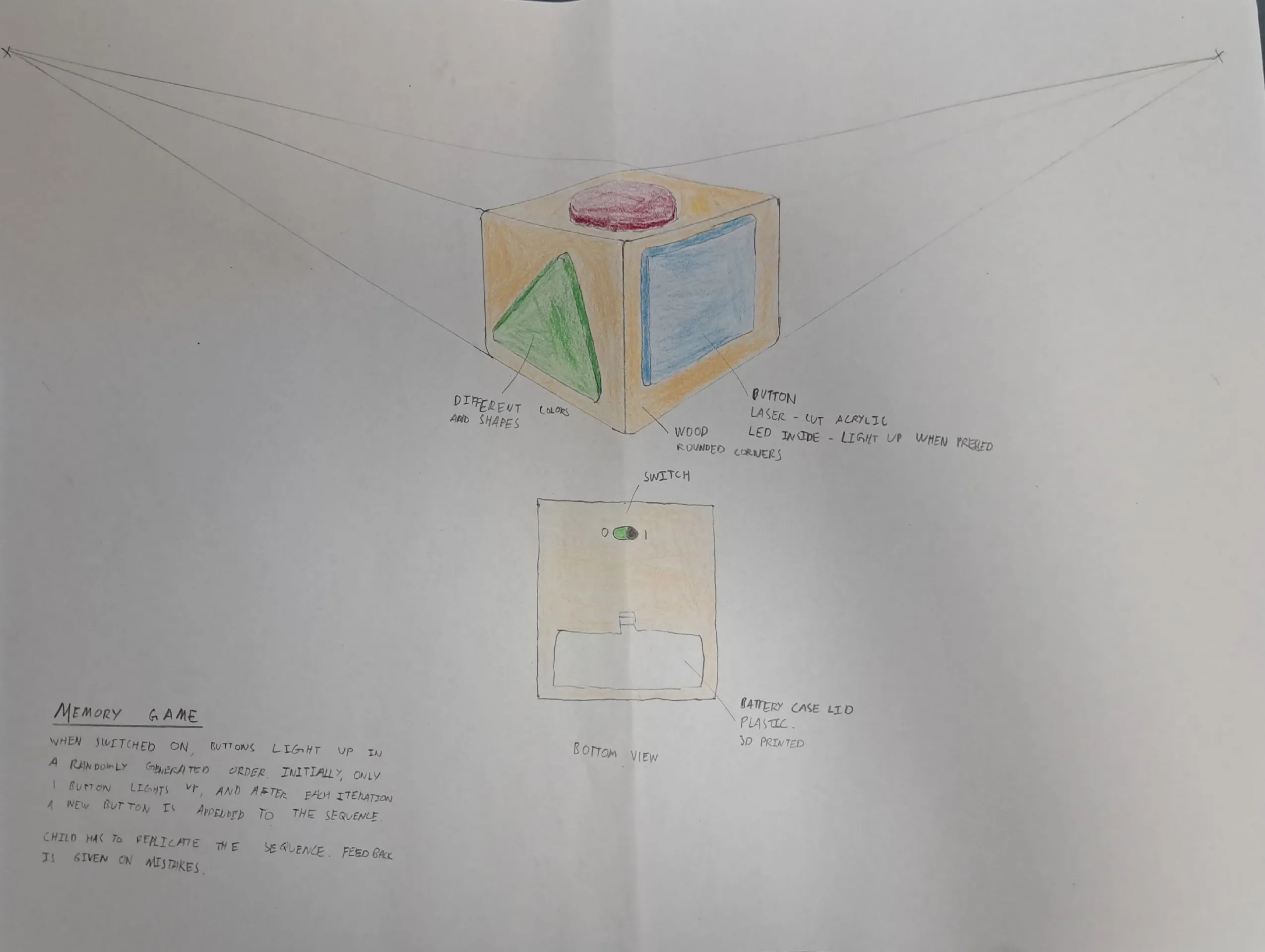
I made some initial sketches of my idea with perspective drawings. The idea to use a cube was motivated by my initial task analysis and research, as the 3D shape could improve the fine motor skills of children in comparison to a simpler 2D flat panel design.
Modelling
To get a better idea of what I was building, I decided to build prototypes (models) out of styrofoam, so I could get early user feedback and understand a reasonable size for the final product, without taking too much time or materials.
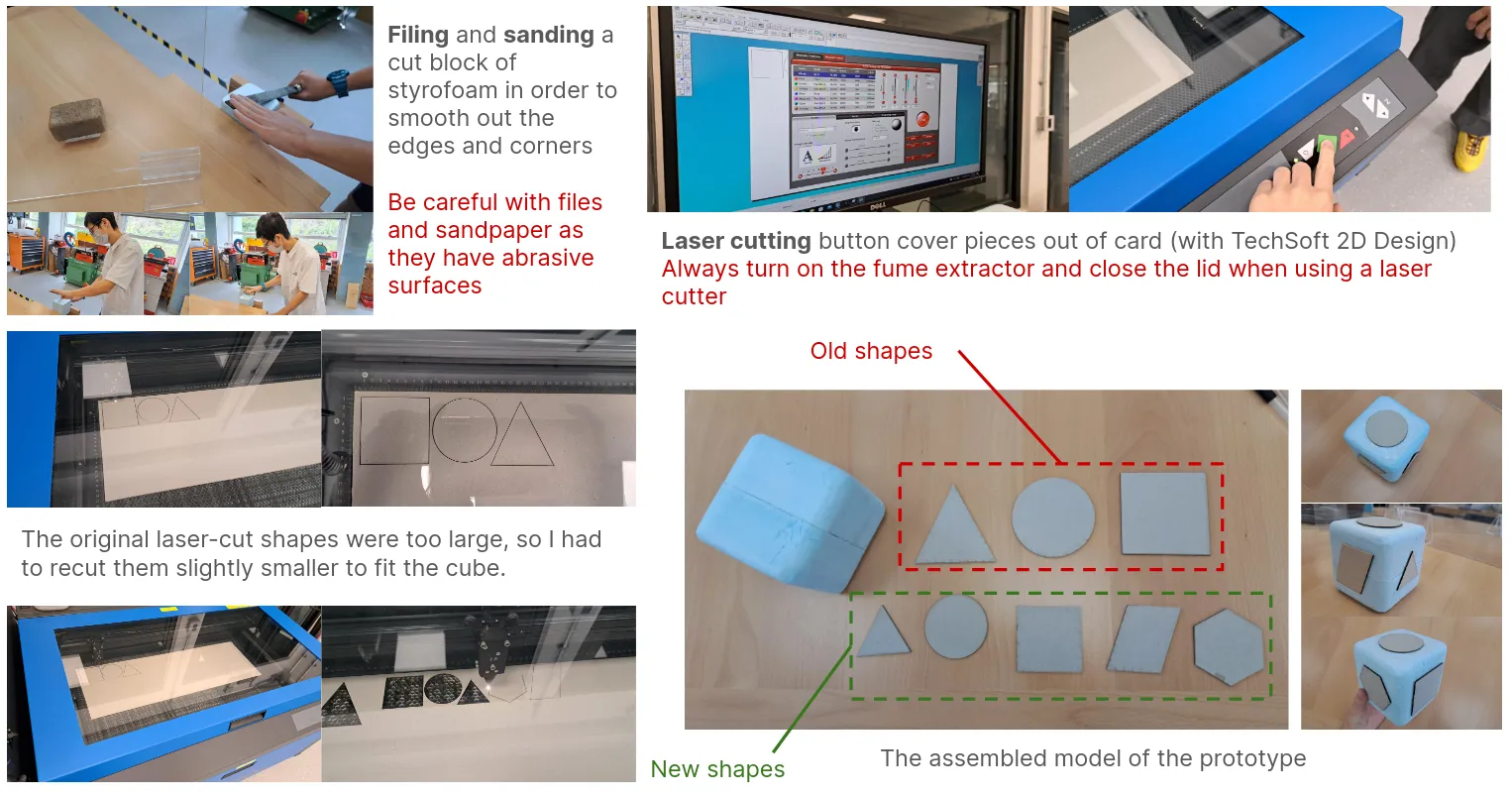
I filed down a styrofoam block, then used the school laser cutter to trim out some cardboard shapes to represent the buttons on the cube.
Buttons
The original idea with the buttons was to couple together a button and a LED to make them light up, like so:
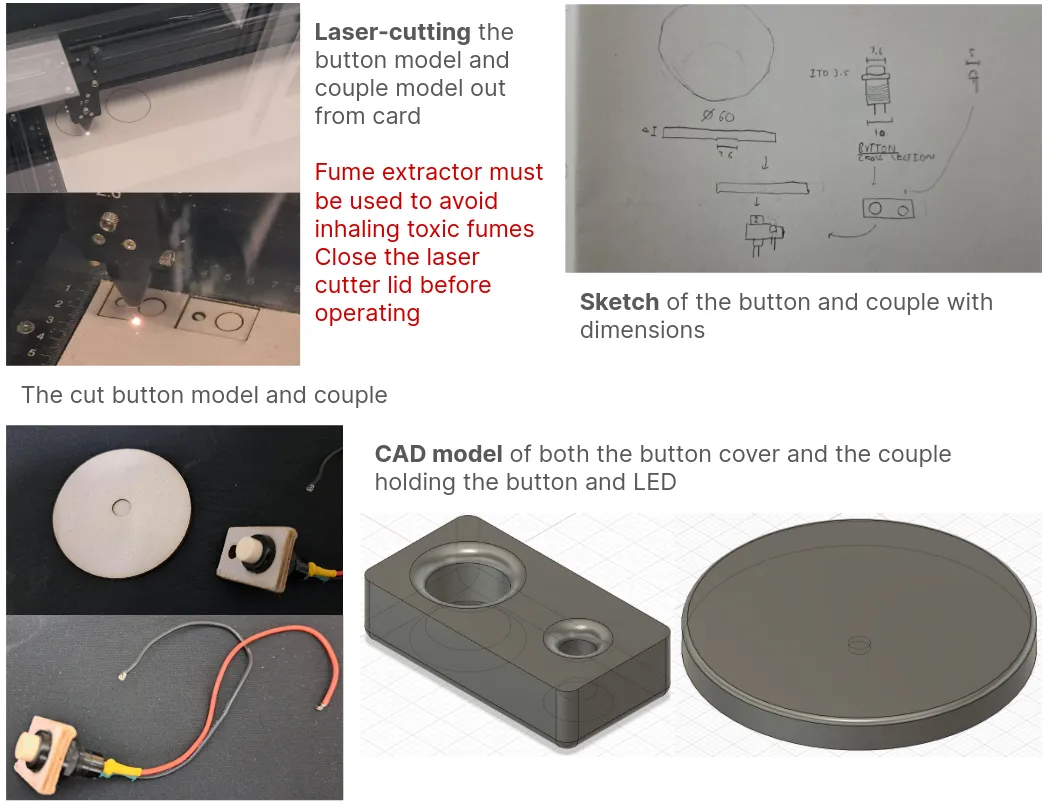
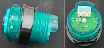
However, this proved to be less aesthetic than pre-made solutions, so I got my hands on some buttons from my computer science teacher.
I made a second model to try out how it would look. It was hot-glued together and the rings that came with the button were used to secure them in the holes.
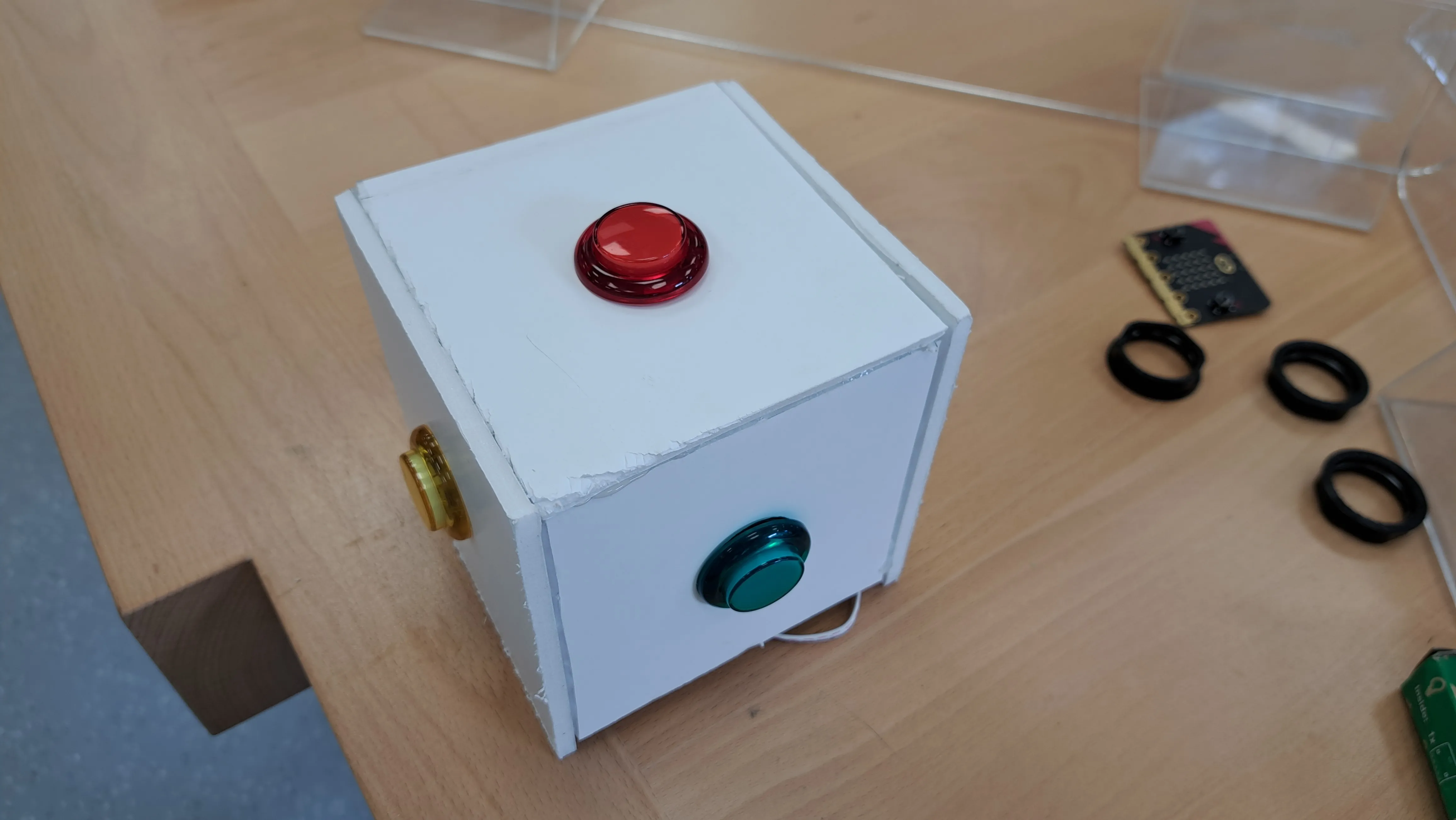
One downside was that I didn’t end up putting the shapes on the buttons, since they would need to not come off and allow the light through.
Magnets
I had thought for a while how I would open up the cube. This would need to be done for two reasons:
- Changing the batteries inside
- In case anything broke, opening the cube was necessary for maintenance
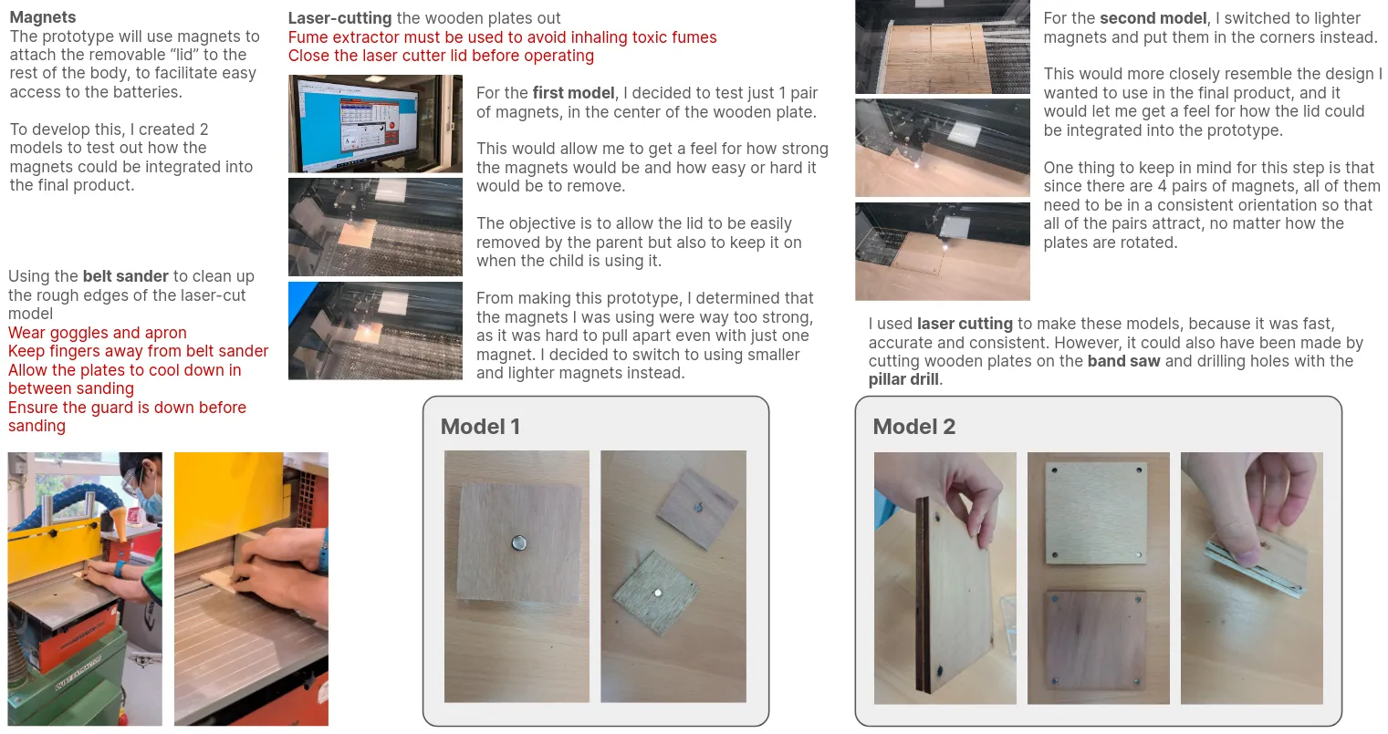
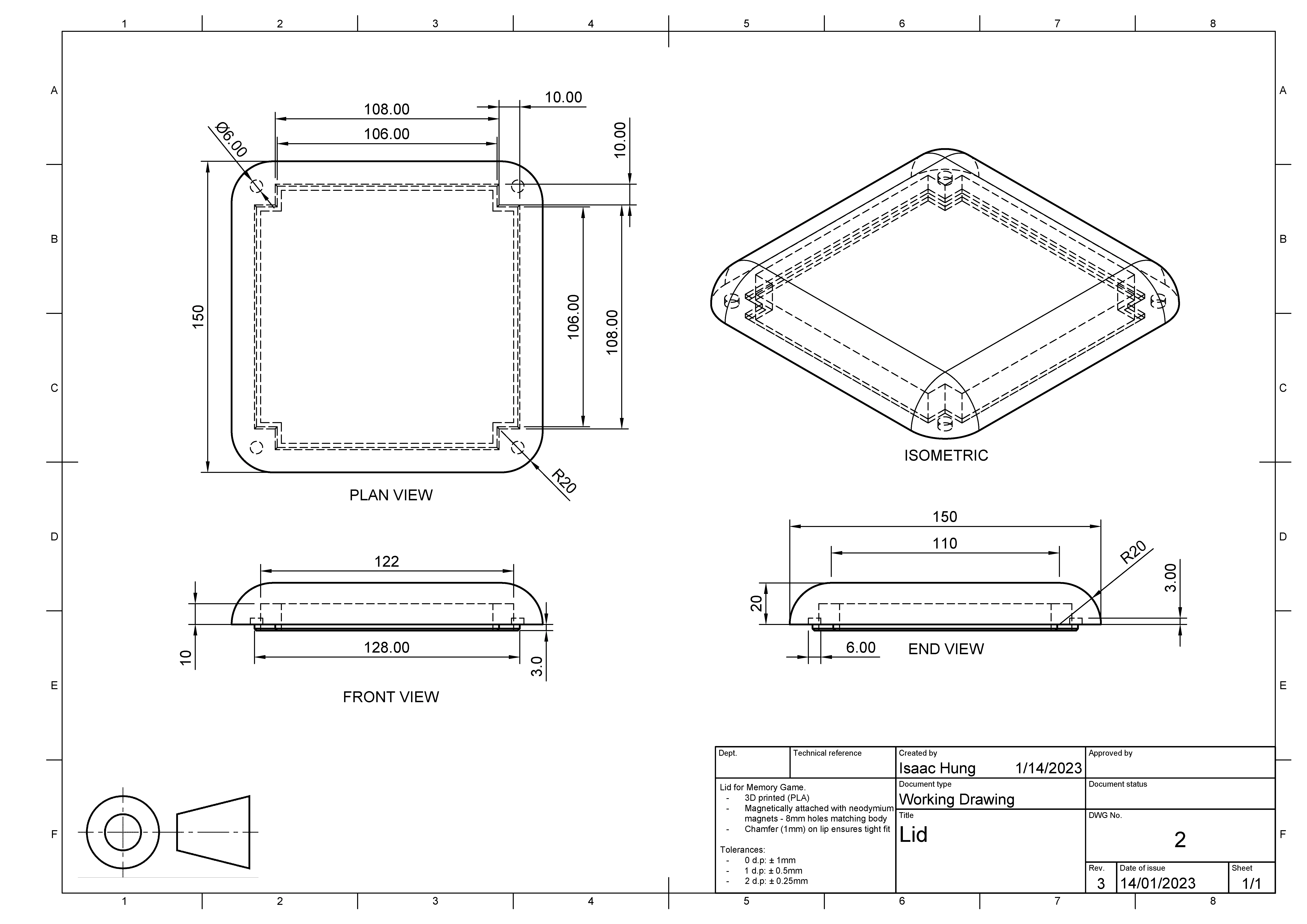
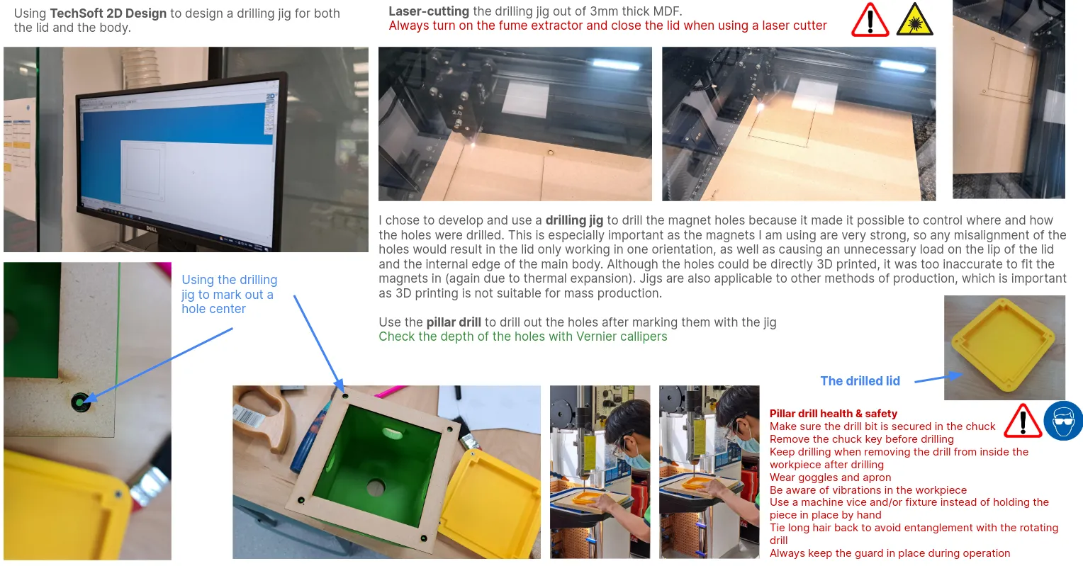
I settled on using 6 mm neodymium magnets to support this. The cube would be designed in two parts, with a main body and a magnetically attachable “lid”, making access easy but ensuring that nothing fell out during operation.
CAD
I used Autodesk Fusion to create CAD models.
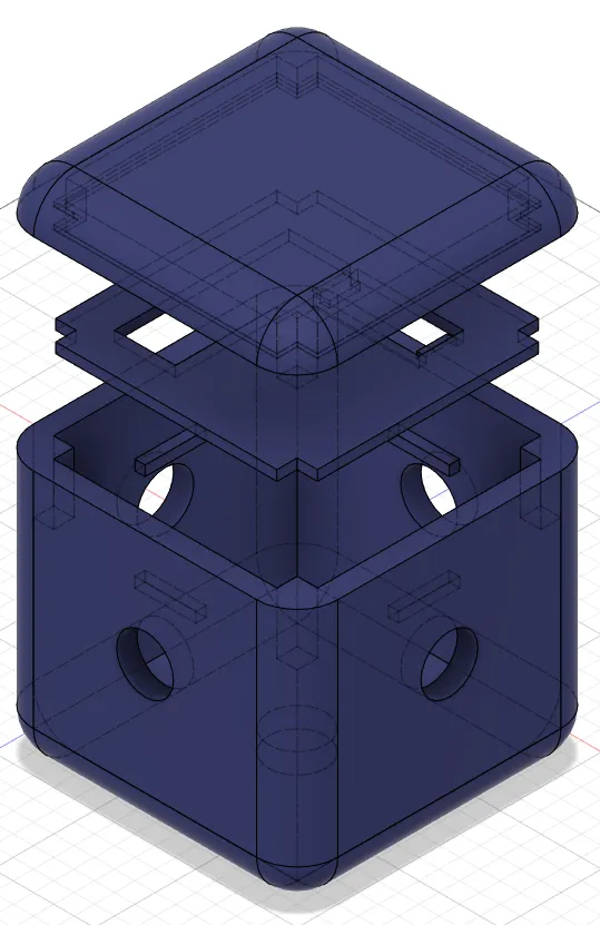
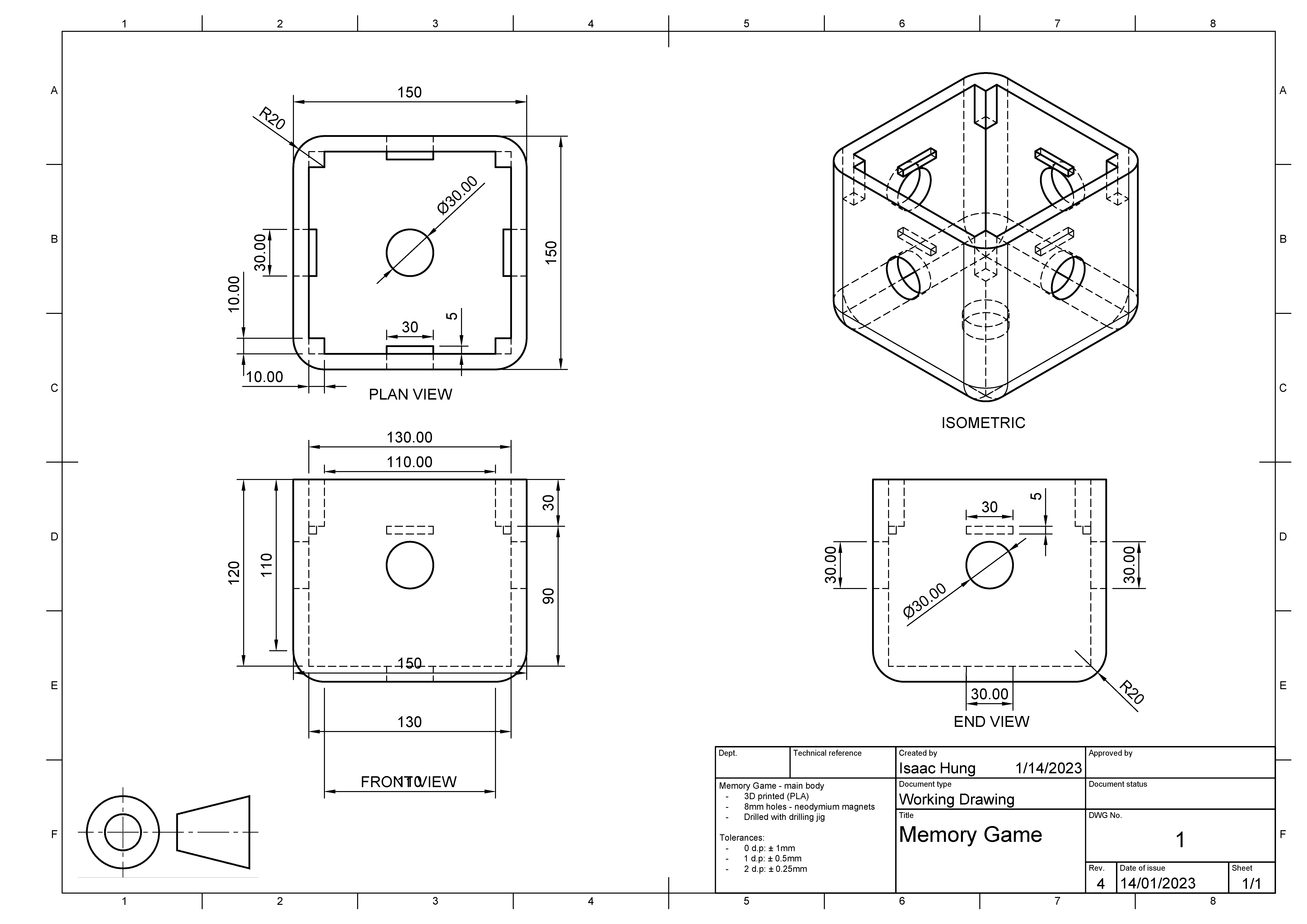
The CAD model was revised many times, ensuring that it met many constraints. For example, the original model had extremely thick walls to keep enough space for the magnets, which resulted in long 3D printing times. To address this, I created an overhang for the magnets specifically.
Working drawings
Main body
Lid
Assembly drawing
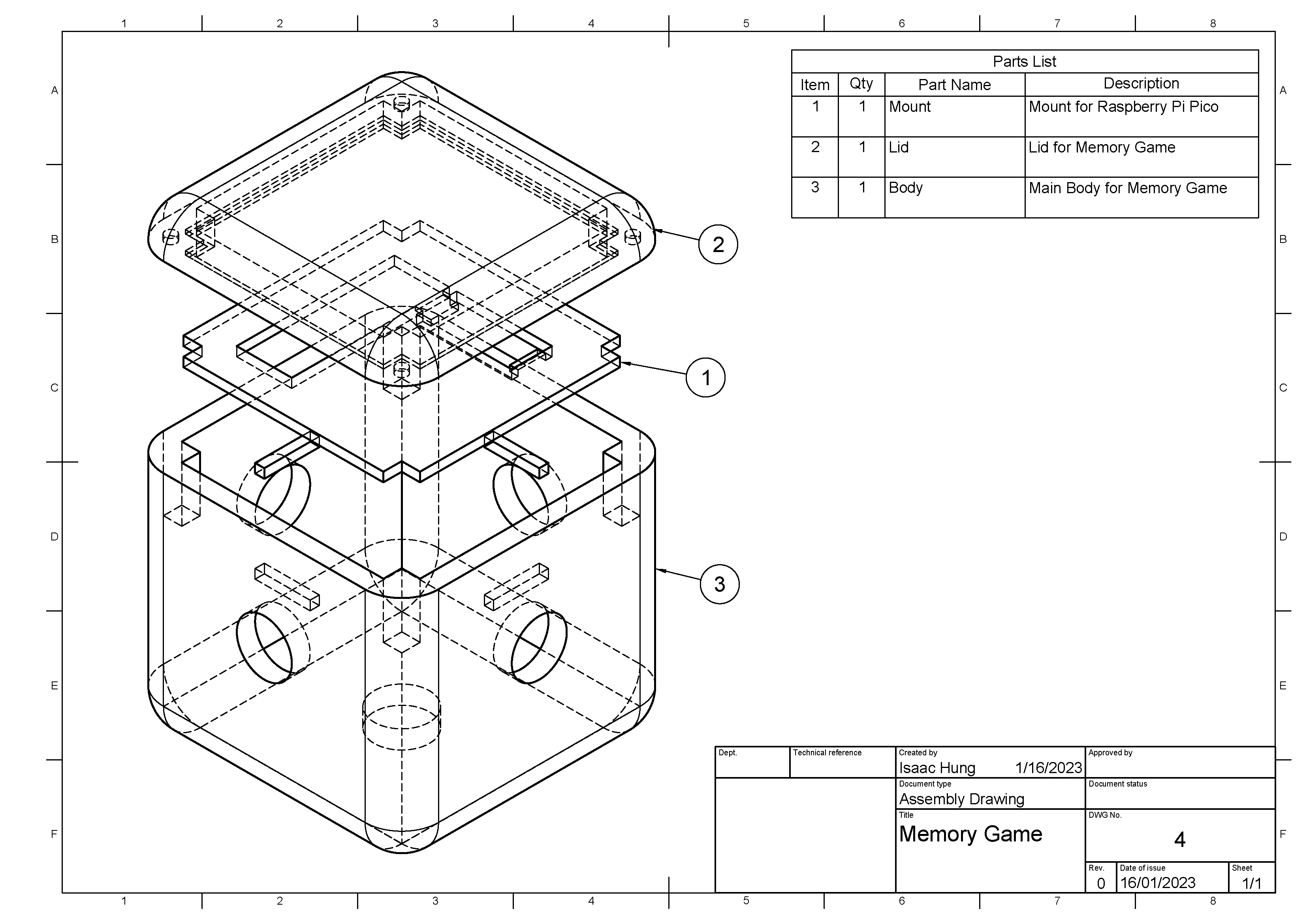
I’ll later discuss the part in the middle, which is used for mounting the microcontroller.
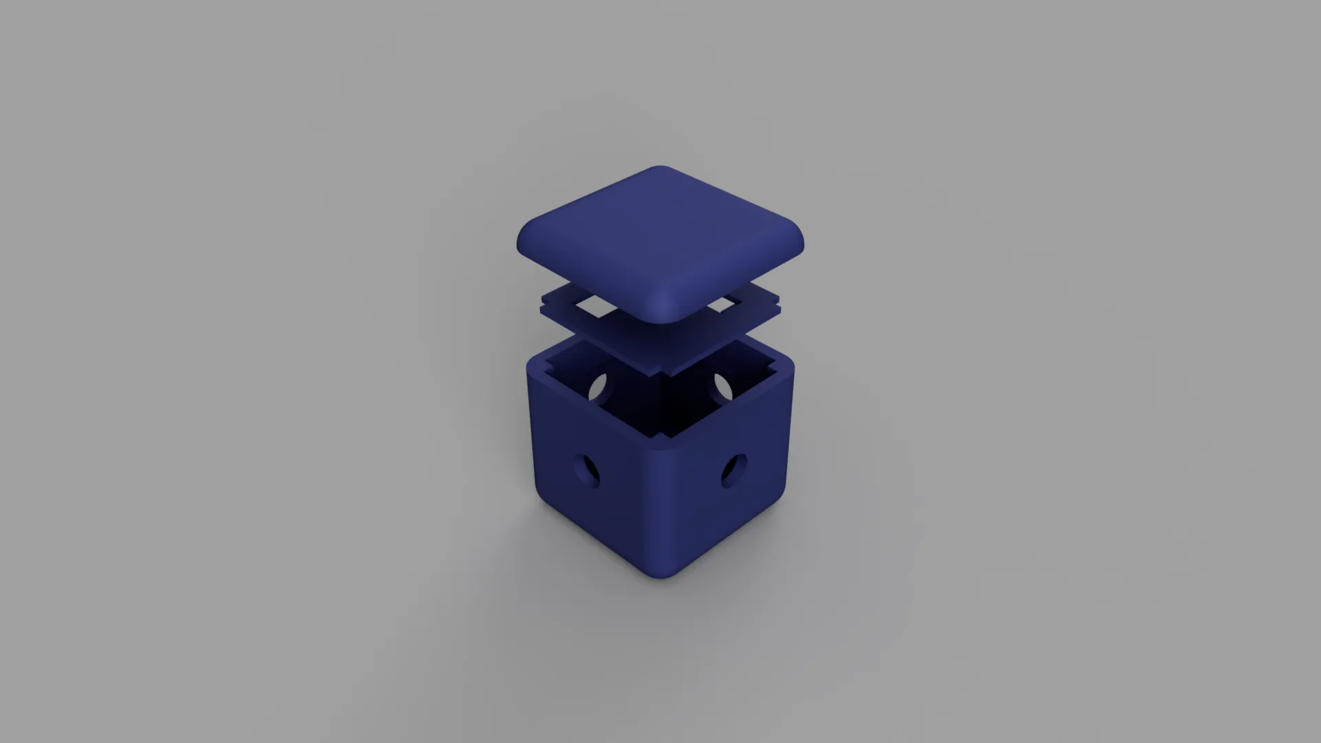
Renders
Electronics and circuit development
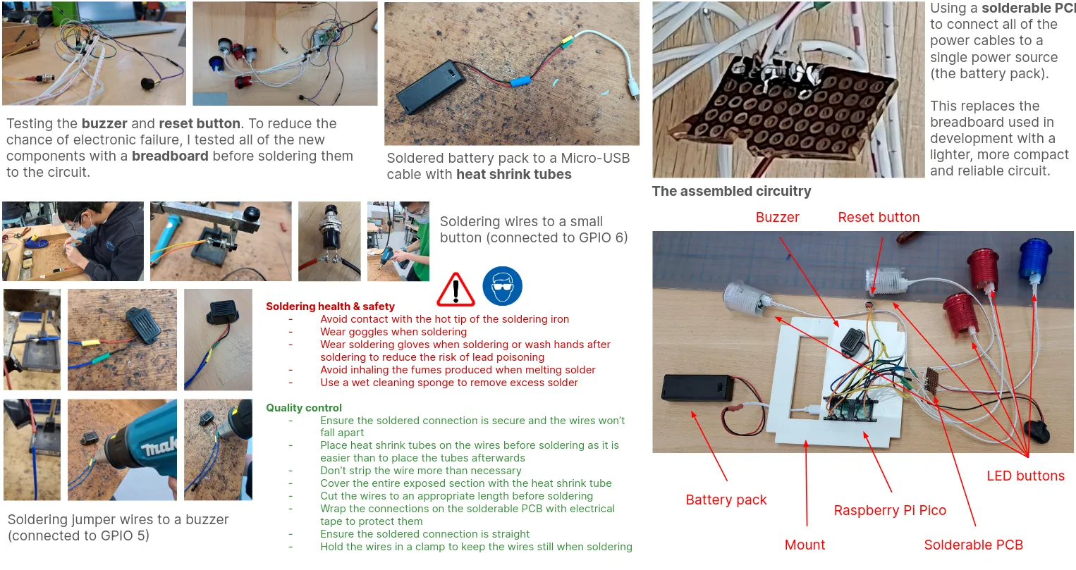
I chose to use the Raspberry Pi Pico to power my project. It is fairly cheap, compact and powerful enough to run MicroPython, which saved time during development.
I started off by connecting a single button to a general-purpose input/output (GPIO) pin and using the MicroPython Pin API to test out one button. Each button has a power (5V), signal and ground line. Using a breadboard made developing the circuitry a lot easier, but thankfully the Pico had enough ground pins to allow each button a unique ground even without breadboards.
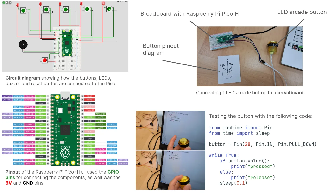
It turns out that the LED buttons I used could actually be controlled through their signal pins. When the button is pressed, the value read is indeed HIGH, but setting the pin’s state from code also worked!
Another fun fact about the buttons: I accidentally broke one and found out that they actually use a mechanical keyboard switch, which produced a nice click feeling!
Here is some sample code that manipulates the behavior of a button:
from machine import Pin
from time import sleep

button = Pin(0, Pin.IN, Pin.PULL_DOWN)

# Flash the LED on and off
button.on()
sleep(1)
button.off()
sleep(1)

# Check if the button is pressed or released
while True:
	if button.value():
		print("Currently pressed")
	else:
		print("Currently released")
After getting one button to work, I then proceeded to add all 5 to the circuit. This was handled in the code by initializing a list of buttons like so:
pins = [Pin(n, Pin.OUT, Pin.PULL_DOWN) for n in range(5)]which worked because I had the buttons on GPIO pins 0-4. I also added a reset button to restart the game and buzzer to complement the LEDs.
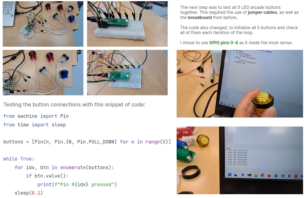
To signify the game being over I flashed every button and the buzzer on and off twice quickly.
Software-hardware integration
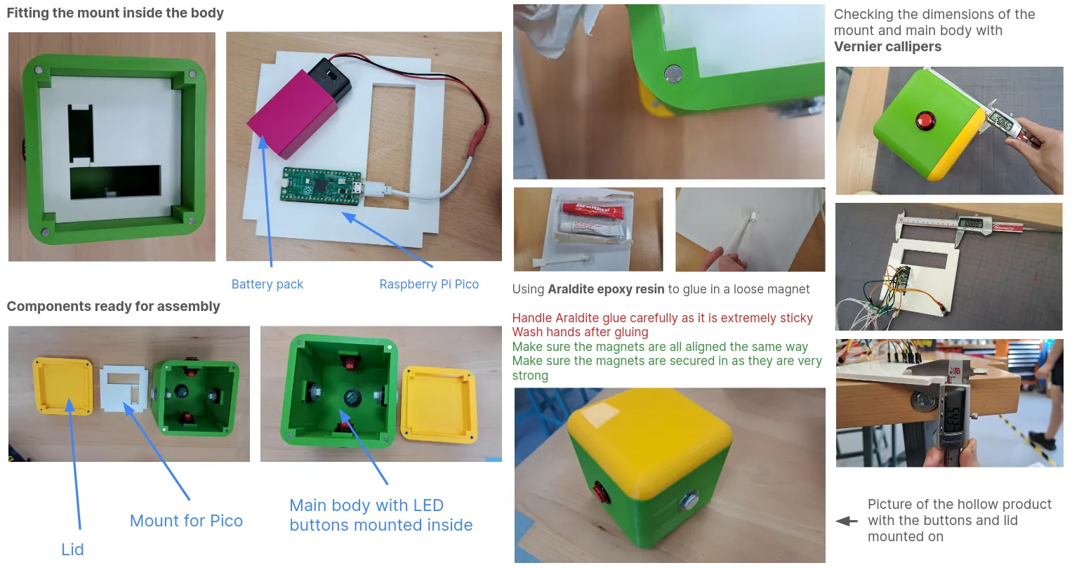
To fit the circuitry inside a cube with no internal flat surfaces (due to the buttons) I had to get creative. I ended up using Vernier calipers to measure the dimensions of the Raspberry Pi Pico accurately, then designing a custom mount for it.
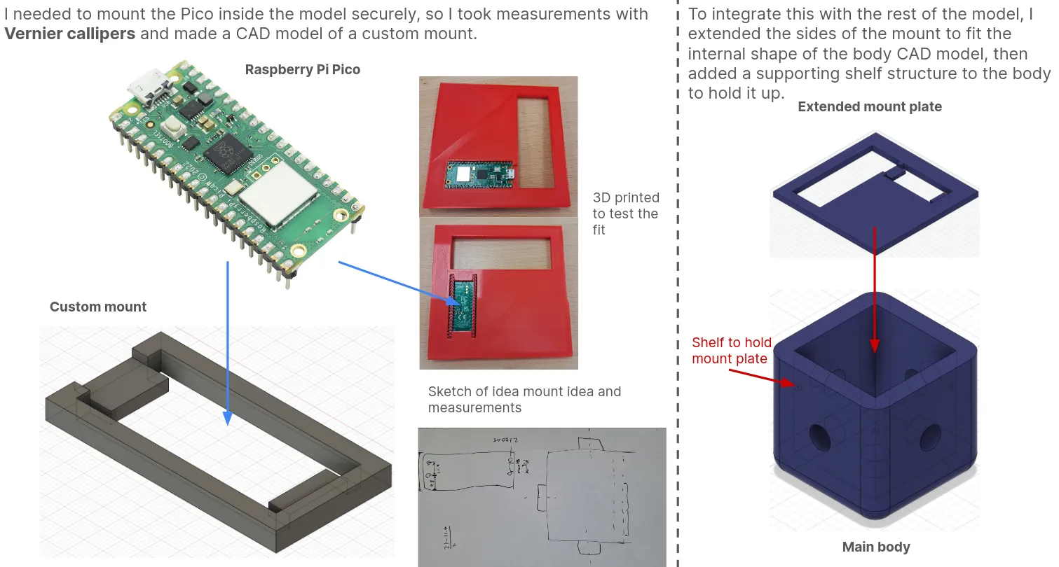
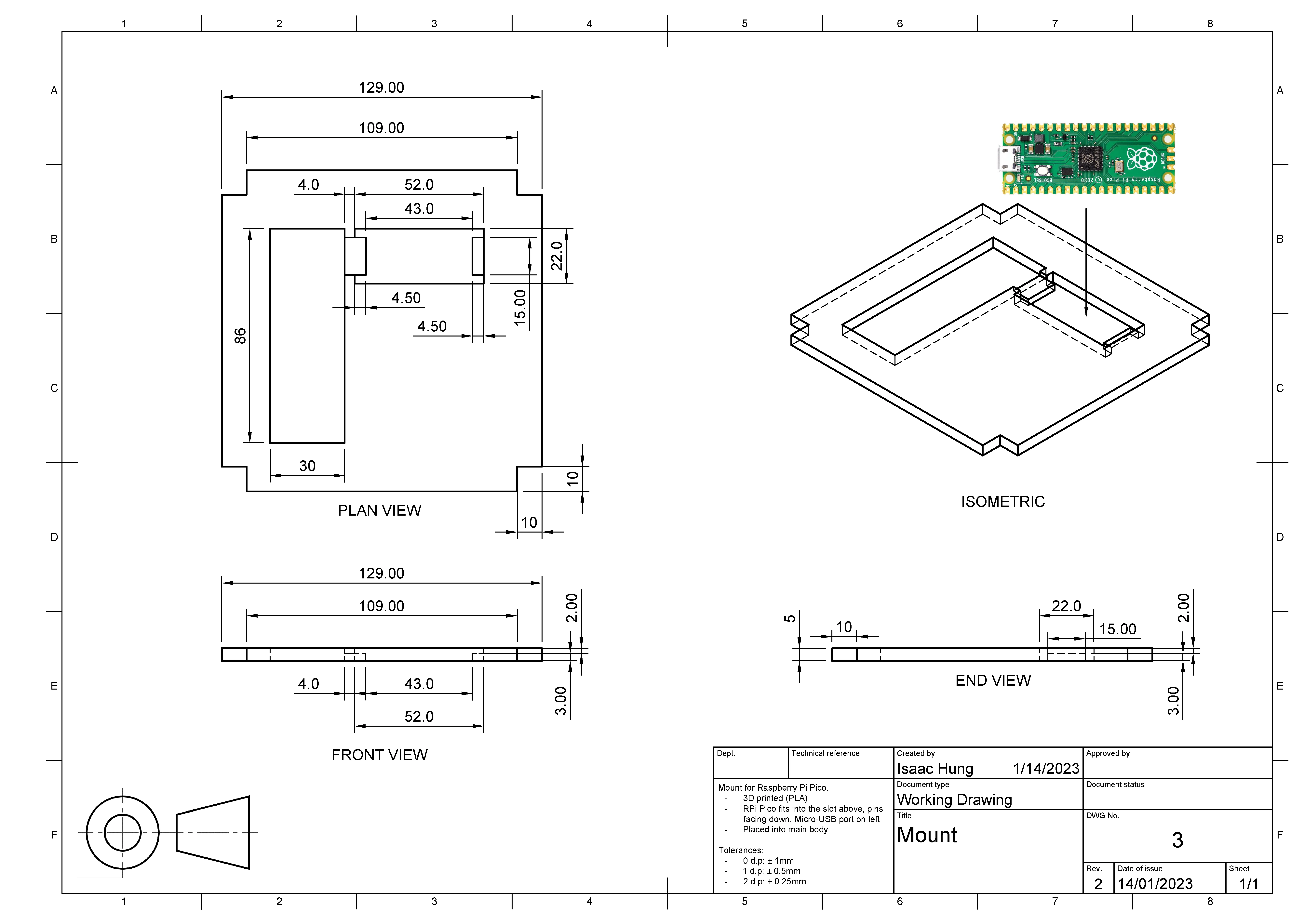
Eventually, after creating overhangs for the magnets, 10x10 mm cuts had to be made in each corner. Here is the final working drawing for the mount:
Hearing the Pico snap perfectly into the freshly-printed mount was one of the most satisfying parts of the build.
Manufacturing
3D printing
Our school uses Ultimaker printers, so I used the Cura slicer to prepare my models for 3D printing.
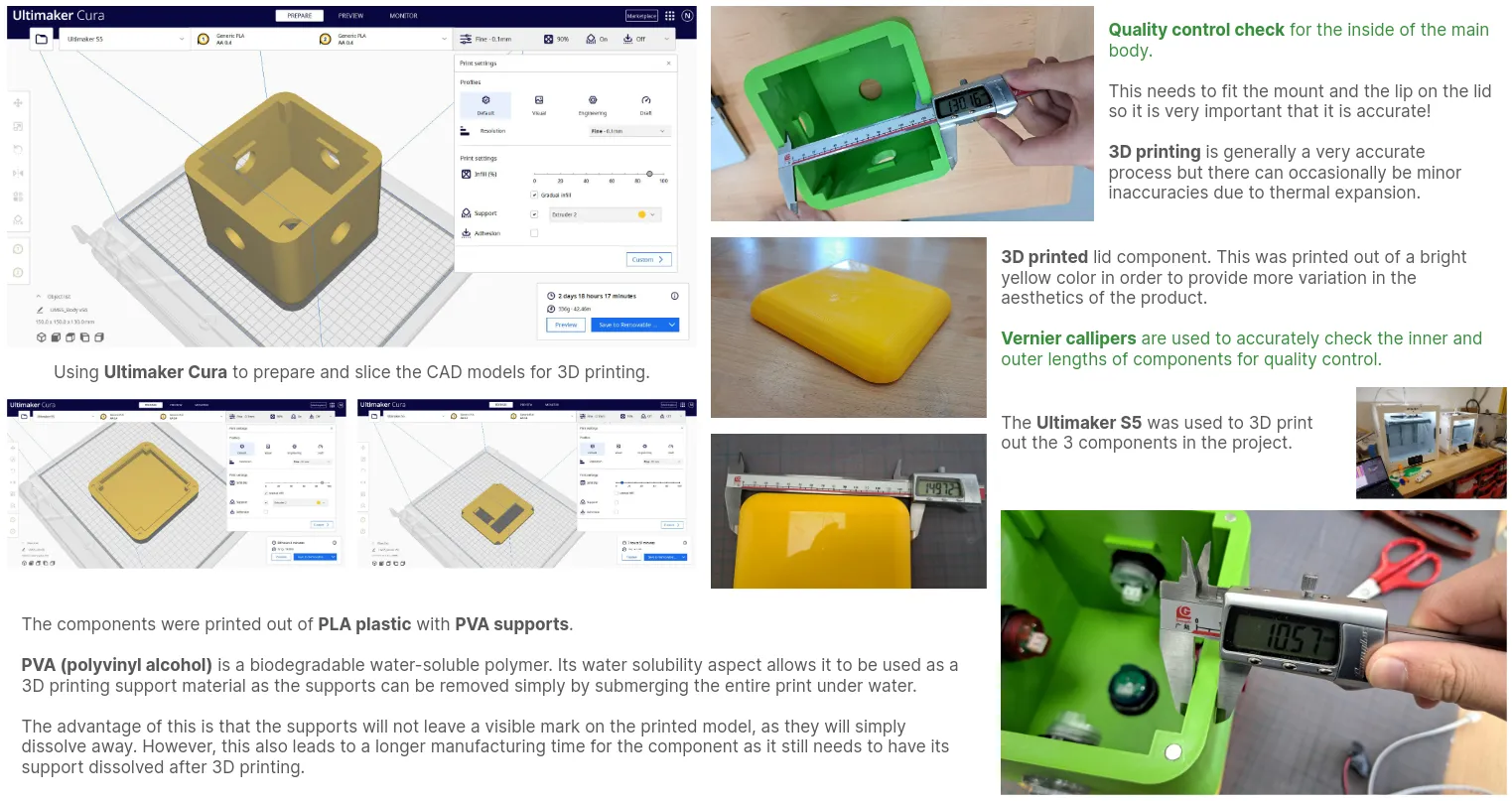
I went with green filament since it was a bright color suitable for toys, and printed the lid in yellow to create a nice contrast. The components themselves were made out of PLA with PVA supports, which would just dissolve when left in water overnight.
In hindsight, although I had already made the walls thinner, I should have tried to do so even further as print times were still long.
Attachment mechanism
Circuitry
Assembly
Conclusion
Creating the memory game toy was an exciting journey that combined creativity, engineering, and problem-solving. Through sketching designs, building prototypes, and integrating electronics, I learned valuable skills and gained hands-on experience.
The project not only enhanced my understanding of interactive toy design but also allowed me to explore the practical applications of programming and CAD modeling. I’m proud of the final product and hope it brings joy and challenges to its users, fostering their memory and motor skills in a fun way!

